
- Details
This page will be updated from time to time as and when required.
| AC | Alternating Current |
| Accessory | A device, other than current-using equipment, associated with such equipment or with the wiring of an installation |
| Bonding Conductor | A protective conductor providing equipotential bonding |
| Circuit | An assembly of electrical equipment supplied from the same origin and protected against overcurrent by the same protective device(s) |
| Circuit-breaker | A device capable of making, carrying and breaking normal load currents and also making and automatically breaking under pre-determined conditions, abnormal currents such as short-circuit currents. It is usually required to operate infrequently although some types are suitable for frequent operation. |
| Class 1 Equipment | Equipment in which protection against electric shock does not rely on basic insulation only, but which includes means for connection of exposed-conductive parts to a protective conductor in a fixed wiring of the insulation |
| Class 2 Equipment | Equipment in which protection against electric shock does not rely on basic insulation only, but in which additional safety precautions such as supplementary insulation are provided, there being no provision for the connection of exposed metal work of the equipment to a protective conductor, and no reliance upon precautions to be taken in the fixed wiring of the installation. |
| Class 3 Equipment | Equipment in which protection against shock relies on supply at SELV and in which voltages higher than those of SELV are not generated. |
| Consumer Unit | A particular type of distribution board comprising a co-ordinated assembly for the control and distribution of electrical energy, principally in domestic premises, incorporating manual means of double pole isolation of the incoming circuit(s) and an assembly of one or more fuses, miniature circuit-breakers, residual current operated devices or signalling and other devices purposely manufactured for such use. |
| CPC | Circuit Protective Conductor - a protective conductor connecting exposed-conductive-parts of equipment to the main earthing terminal |
| Current | Measured in Amperes or Amps it is the flow of a charge when a voltage is applied |
| Current-using equipment | Equipment which converts electrical energy into another form of energy, such as a light, heat or motive power. |
| DC | Direct Current |
| Distribution Board | An assembly containing switching or protective devices (e.g. fuses, circuit breakers, residual current operated devices) associated with one or more outgoing circuits fed from one or more incoming circuits, together with terminals for the neutral and protective circuit conductors. It may also include signalling and other control devices. Means of isolation may be included in the board or may be provided separately. |
| Earth | The conductive mass of the Earth, whose electric potential at any point is conventionally taken as zero |
| Earth electrode | A conductor or group of conductors in intimate contact with, and providing an electrical connection to, Earth |
| Earthing | Connection of exposed-conductive-parts of an installation to the main earthing terminal of that installation. |
| Earthing conductor | A protective conductor connecting the main earthing terminal of an installation to an earth electrode or to other means of earthing |
| Electric shock | A dangerous physiological effect resulting from the passing of an electric current through a human body or livestock |
| Electrical installation | An assembly of associated electrical equipment supplied from a common origin to fulfill a specific purpose and having certain co-ordinated characteristics. |
| ELV | Extra Low Voltage normally not exceeding 60 V a.c. or 120 V ripple free d.c., whether between conductors or to Earth. |
| Equipotential bonding | Electrical connection maintaining various exposed-conductive-parts and extraneous-conductive-parts at substantially the same potential |
| Exposed-conductive-part | A conductive part of equipment which can be touched and which is not a live part but which may become live under fault conditions. |
| Extraneous-conductive-part | A conductive part liable to introduce a potential, generally earth potential, and not forming part of the electrical installation |
| Fault | A circuit condition in which current flows through an abnormal or unintended path. This may result from an insulation failure or a bridging of insulation. Conventionally the impedance between live conductors or between live conductors and exposed- or extraneous-conductive parts at the fault position is considered negligible. |
| Fault current | A current resulting from a fault |
| Fuse | A device which by the fusing of one or more of its specially designed and proportioned components, opens the circuit in which it is inserted by breaking the current when this exceeds a given value for a sufficient time. The fuse comprises all the parts that form the complete device. |
| Insulation | Suitable non-conductive material enclosing, surrounding or supporting a conductor. |
| Isolation | A function intended to cut off the reasons of safety the supply from all, or discrete section, of the installation by separating the installation or section from every source of electrical energy. |
| Isolator | A mechanical switching device which, in the open position, complies with the requirements specified for isolation. An isolator is otherwise known as a disconnector. |
| Live Part | A conductor or conductive part intended to be energised in normal use, including a neutral conductor but, by convention, not a PEN conductor. |
| Luminaire | Equipment which distributes, filters or transforms the light from one or more lamps, and which includes any part necessary for supporting, fixing and protecting the lamps, but not the lamps themselves, and, where necessary, circuit auxiliaries together with the means for connecting them to the supply. For the purposes of the regulations a lampholder, however supported, is deemed to be a luminaire. |
| LV | Low Voltage normally exceeding extra-low voltage but not exceeding 1000 V a.c. or 1500 V d.c. between conductors, or 600 V a.c. or 900 V d.c. between conductors and Earth. |
| Main earthing terminal | The terminal or bar provided for the connection of protective conductors, including equipotential bonding conductors, and conductors for functional earthing, if any, to the means of earthing. |
| MCB | Miniature Circuit Breaker acts in a similar way to fuse. |
| Neutral conductor | A conductor connected to the neutral point of a system and contributing to the transmission of electrical energy. The term also means the equivalent conductor of an IT or d.c. system unless otherwise specified in the Regulations. |
| PELV | Protective Extra-Low Voltage - An extra-low voltage system which is not electrically separated from earth, but which otherwise satisfies all the requirements for SELV |
| PEN conductor | A conductor combining the function of both protective conductor and neutral conductor. |
| Phase conductor | A conductor of an a.c. System for the transmission of electrical energy other than a neutral conductor, a protective conductor or a PEN conductor. The term also means the equivalent conductor of a d.c. System unless otherwise specified in the Regulations. |
| PME | Protective Multiple Earthing - An earthing arrangement, found in TN-C-S systems, in which the supply neutral conductor is used to connect the earthing conductor of an installation with Earth, in accordance with the Electrical Supply Regulations 1988 as amended. |
| Power | Measured in Watts it is the rate of energy transfer, Amps, when a voltage is applied |
| Protective Conductor | The earth cable or conductor in a circuit |
| RCBO | Residual Current Breaker with integral Overcurrent protection is similar to an RCD but also has the added function of an MCB |
| RCCB | Residual Current Circuit Breaker similar to an RCBO |
| RCD | Residual Current Device a mechanical switching device or association of devices intended to cause the opening of the contacts when the residual current attains a given value under specified conditions. |
| SELV | Separated Extra Low Voltage an extra-low voltage system which is electrically separated from Earth and from other systems in such a way that a single fault cannot give rise to the risk of electric shock. |
| TN System | Terre Neutre a system having one or more points of the source of energy directly earthed, the exposed-conductive-parts of the installation being connected to that point by protective conductors. |
| TN-C-S System | Terre Neutre - Combined - Separated a system in which the neutral and protective functions are combined in a single conductor in part of the system. |
| TN-S | Terre Neutre - Separated a system having separate neutral and protective conductors throughout the system |
| TT | A system having one point of the source of energy directly earthed, the exposed-conductive-parts of the installation being connected to earth electrodes electrically independent of the earth electrodes of the source |
| VAC | Volts Alternating Current |
| VDC | Volts Direct Current |
| Voltage bands |
Band 1 covers Band 2 |
| Voltage, nominal |
Voltages by which an installation (or part of an installation) is designed. The following ranges of nominal voltage (rms values for a.c. are defined: The actual voltage of the installation may differ from the nominal value by a quantity within normal tolerances |
- Details
This comes under the realms of SPECIAL LOCATION and is classified as a room containing a shower with or without a shower basin or a room containing a bath tub. It is classed as a 'Special Location' due to the higher than usual risk of electrical injury due to low body resistance when wet.
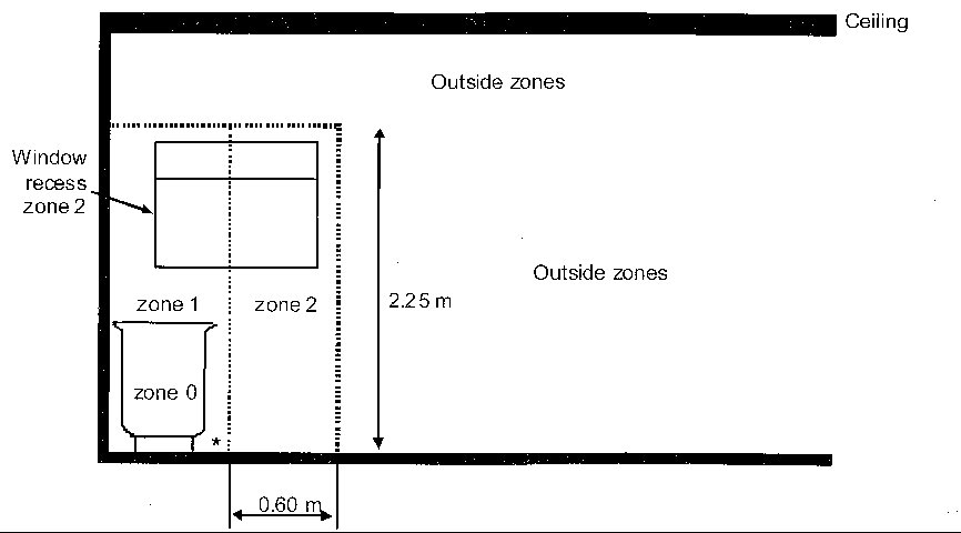
The Regulations define ZONES for rooms containing a bath tub or shower with or without a basin. Only certain accessories or fixed appliances can be reasonably located in certain Zones dependent on the Index of Protection of the individual item. The following describes the Zones:
Zone 0 is the interior of the bath tub or shower basin.
For showers without a basin, the height of zone 0 is 0.10 m and its surface extent has the same horizontal extent as
zone 1
Zone 1 is limited by:
(i) the finished floor level and the horizontal plane corresponding to the highest fixed shower head or water
outlet or the horizontal plane lying 2.25 m above the finished floor level, whichever is higher
(ii) the vertical surface:
(a) circumscribing the bath tub or shower basin
(b) at a distance of 1.20 m from the centre point of the fixed water outlet on the wall or ceiling for showers
without a basin.
Zone 1 does not include zone 0.
The space under the bath tub or shower basin is considered to be zone 1. However, if the space under the bath tub or
shower basin is only accessible with a tool, it is considered to be outside the zones.
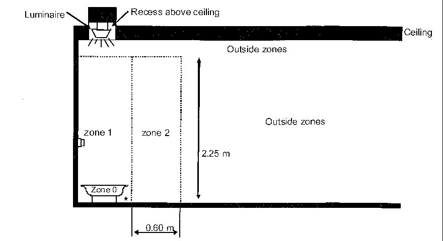
Zone 2 is limited by:
(i) the finished floor level and the horizontal plane corresponding to the highest fixed shower head or water
outlet or the horizontal plane lying 2.25 m above the finished floor level, whichever is higher
(ii) the vertical surface at the boundary of zone 1 and the parallel vertical surface at a distance of 0.60 m from
the zone 1 border. .
For showers without a basin, there is no zone 2 but an increased zone 1 is provided by the horizontal dimension of
1.20 m.
Bath tub
Click to enlarge in new window
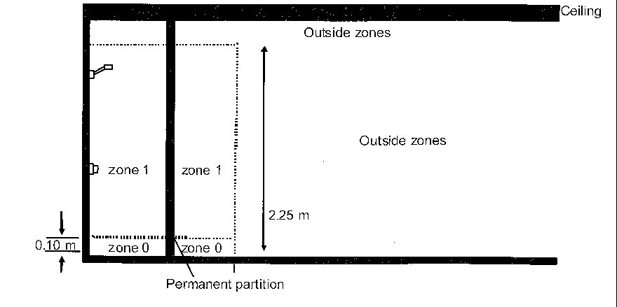
Bath tub, with permanent fixed partition
Click to enlarge in new window
Shower basin
Click to enlarge in new window
Shower basin, with permanent fixed partition.
Click to enlarge in new window
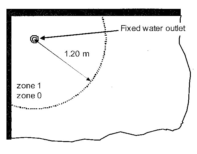
Shower without basin
Click to enlarge in new window
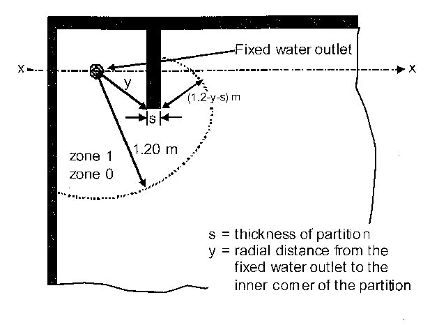
Shower without basin, but with permanent fixed pasrtition
Click to enlarge in new window
Bath tub
Click to enlarge in new window
Shower basin
Click to enlarge in new window
Shower without basin, but with perninent fixed partition.
Click to enlarge in new window
Bathroom Zones and Switches, Controls,Accessories
Care should be taken as to where accessories and fixed current using equipment are installed within the bathroom in order to satisfy the Wiring Regulations. The following are examples of the most common accessories and fixed current using equipment which are permitted in different zones:-
Zone 0 IPX7 equipment, NO switches or accessories.
Zone 1 IPX4 Equipment and SELV switches with the source outside all the zones.
Zone 2 IPX4 Anything from Zone's 0,1 Unswitched spurs, flex outlets. Shaver points that are to BS EN 61558-2-5 can be fitted in Zone 2 providing they are not in the direct line of the water jet.
Outside Zones Anything from Zone's 0, 1, & 2. Anything goes providing it is deemed suitable to be used in the bathroom and is fixed, NOT portable. Sockets, except SELV sockets, must not be fitted closer than 3 metres horizontally from the border of Zone 1
Current using equipment
Zone 0
The equipment meets IPX7 and relevant standards according to manufacturers instructions.
It is fixed and permanantly connected to a supply.
The equipment is connected to a SELV supply with the source outside the zones.
Zone 1
Only the following can be fitted providing they are suitable for the zone, IPX4, or suitable according to manufacturers instructions:
Whirlpool units
Electric Showers
Shower Pumps
Equipment protected by SELV
Ventilation equipment
Towel Rails
Water heater appliances
luminaires.
Electric floor heating
For electric floor heating systems, only heating cables according to relevant product standards or thin sheet sheet flexible heating elements according to relevant equipment standard shall be erected provided that they have either a metal sheath or a metal enclosure or a fine mesh metallic grid. The fine mesh metallic grid, metal sheath or metal enclosure shall be connected to the protective conductor of the supply circuit. Compliance with the latter requirement is not required if the protective measure SELV is provided for the floor heating system.
For electric floor heating systems the protective measure 'protection by electrical separation' is not permitted.
RCD's
All electrical items in the bathroom should be RCD protected at 30mA.
Manufacturers of certain electrical equipment ask for RCD's to be fitted for the supplementary protection of the equipment, read the instructions.
NOTE: If RCD's are not installed and/or protective equipotential bonding is not in place then local supplementary bonding must be installed.
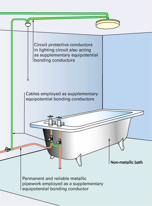
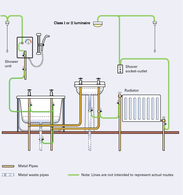
Supplementary Bonding
All electrical sources, lights, electric heaters, showers etc. have to be connected together along with the pipe work. It does not have to be one continuous cable as long as there is an electrical continuity between everything locally within the room. The cable size is normally 4mm² and you should use the BS951 Earthing Clamps on pipe work. If you have a new shower fitted in your bathroom you will more than likely have to have this bonding updated which of course will add additional costs to the installation. By having everything earthed together, should there be a fault to earth, there will be the same potential all round the bathroom thereby any electric shock should be minimal.
Click on either image to enlarge
(It will open in a new window)
- Details
Circuits are important in the fact that without them you would not be able to run your TV, HiFi, lights etc. Your circuits are supplied direct from your Fuse Board/Consumer Unit and form Part of what is known as the Electrical Installation. An Electrical Installation in general is all the circuits, accessories etc within your property.
Circuits are referred to by a name and number with the lowest number normally being next to the main isolation switch of the fuse board. Furthermore it is good practice having the largest Fuse/MCB next to the main switch or in the case of a split load boards, and where relevant, next to the RCD or RCBO on the protected side. Modern day fuse boards could have the main switch on the left or on the right. the RCD/RCBO whilst normally being midway it has been known for them to be situated on the opposite end to the main switch.
Below is typical modern day layout of a fuse board in a house
Main Switch 100A Double pole to BS 60947-3
|
Circuit Designation
|
Circuit Name
|
Fuse Size (Amps)
|
Fuse Type
|
Cable Size Twin & Earth (mm²) |
Phase conductor size (mm²)
|
Neutral conductor size (mm²)
|
CPC (Earth) conductor size (mm²)
|
Notes
|
|
1 or 8
See Notes |
Cooker
|
32 or 40
|
B
|
6 or 10
|
6 or 10
|
6 or 10
|
2.5 or 4
|
If the cooker isolation switch incorporates a socket it should be on the RCD protected side and 'Immersion' would therefore take circuit 1 |
|
2
|
Immersion
Central Heating |
16
|
B
|
2.5 |
2.5
|
2.5
|
1.5
|
|
|
3
|
Lights Up Stairs
|
6
|
B
|
1 or 1.5 |
1 or 1.5
|
1 or 1.5
|
1
|
Properties normally have 2 light circuits regardless as to weather it is a flat, bungalow or house. This means that if if one light circuit fails, there is still some form of lighting. |
|
4
|
Lights Down Stairs
|
6
|
B
|
1or 1.5
|
1 or 1.5
|
1 or 1.5
|
1
|
As per Lights Up |
|
5
|
Smoke Alarms
|
6
|
B
|
1 or 1.5
|
1 or 1.5
|
1 or 1.5
|
1
|
Modern domestic smoke alarms can have two power sources, Battery and Mains. |
|
6
|
Spare
|
RCD 80A 30mA Double Pole
The following circuits have additional protection from the RCD
|
Circuit Designation
|
Circuit Name
|
Fuse Size (Amps)
|
Fuse Type
|
Cable Size Twin & Earth (mm²) |
Phase conductor size (mm²)
|
Neutral conductor size (mm²)
|
CPC (Earth) conductor size (mm²)
|
Notes
|
|
7
|
Shower
|
40
|
B
|
10
|
10
|
10
|
4
|
|
|
1 or 8
|
Cooker
|
32 or 40
|
B
|
6 or 10 |
6 or 10
|
6 or 10
|
2.5 or 4
|
See Notes for Circuit 1 |
|
9
|
Kitchen Ring
|
32
|
B
|
2.5
|
2.5
|
2.5
|
1.5
|
As the kitchen tends to draw the largest amount of power it is a good idea for it to have its own separate supply |
|
10
|
Upstairs Ring
|
32
|
B
|
2.5
|
2.5
|
2.5
|
1.5
|
|
|
11
|
Downstairs Ring
|
32
|
B
|
2.5
|
2.5
|
2.5
|
1.5
|
|
|
12
|
Spare
|
- Details
The route the cable is going to take, in conduit, trunking, walls, touching thermal insulation, clipped to walls, etc., (The same size cable clipped to a normal wall or chased in a normal wall will carry more load than the same size and type of cable installed in trunking, conduit or touching thermal insulation).
Will the cable be grouped with or touching other cables. (This will down grade the current capacity of the cable slightly).
The length of cable to be used, total length of the circuit from the fuse board to the appliance. (The longer the cable, the more voltage that is lost in the cable due to the resistance of the cable. Only a maximum volt drop of 4% is permitted by the regulations).
The environment the cable is surrounded by, in sunlight, high ambient temperatures, exposed to the elements, extreme cold, fauna etc. (Installation of the wrong type of cable in an environment will mean frequent maintenance)
The size of fuse protection. (If the fuse is too great and there is a fault, you risk the possibility of starting a fire).
In order to comply with the regulations, any buried cables, be it in walls, under the floor, or in ceilings, must be at the correct depth and run in specific areas. Care must also be taken not to place them in areas where they will be susceptible to external influences such as heat sources or mechanical damage. If the cable is installed in trunking or conduit, on the surface, there are no prescribed areas providing it looks neat.
When installing cables carrying different voltages such as LV and ELV it is important that they are segregated so that LV circuits do not induce a current in the ELV circuit.
Care should be taken not to crowd trunking with multiple cables. As a guide, trunking should be filled to a maximum of 45% of its capacity.
Cables in Walls
Cables through joists
Notes:
1 Maximum diameter of hole should be 0.25 x joist depth
2 Holes on centre line in a zone between 0.25 and 0.4 x span
3 Maximum depth of notch should be 0.125 x joist depth.
4 Notches on top in a zone between 0.1 and 0.25 x span.
5 Holes in the same joist should be at least 3 diameters apart.
- Details
Light circuits are generally installed using 1.0 mm² or 1.5 mm² Twin & Earth cable. The picture shown below is a typical wiring diagram for a lighting circuit by today's standards. There are, of course, variations eg, older wiring may not include an earth conductor or the earth may be the steel conduit that the conducts are placed in. The represented switch is a two way light switch wired as a one way. You may find additional conductors if the light is being controlled from more than one location. Furthermore use caution when working on these circuits as it has been found that they have been wired incorrectly or there is no Red Sleeving or Red PVC Tape fitted to identify the Live conductors. All earth conductors must be identified using Green/Yellow Sleeving. Some older installations will be using Green Sleeving to identify earth which was acceptable at the time. REMEMBER, before working on circuits previously energised, ensure Safe Isolation
OLD COLOURS
.
Click image to enlarge
(It will open in a new window)
REMEMBER GREEN REPRESENTS GREEN/YELLOW CONDUCTOR IDENTIFICATION
NEW COLOURS
.
Click image to enlarge
(It will open in a new window)
REMEMBER GREEN REPRESENTS GREEN/YELLOW CONDUCTOR IDENTIFICATION
Before replacing the light fitting, be sure to safely isolate the circuit (See Safe Isolation).
If there is no form of earthing in the lighting circuit and the light accessory requires one, you must install it.
If the light accessory is to be installed in the bathroom it must be included with the supplementary bonding. If there is no earth conductor between the light switch and the light fitting one must be installed either using a 1 mm² or 1.5 mm² conductor. Connect the earth terminal in either the switch or in the light fitting with 4 mm² and connect the other end to some part of the supplementary bonding already in place (See bathrooms). If the light circuit in the bathroom is not to be included with the supplementary bonding, because it falls outside the bathroom zones,or is exterior to the bathroom, then you must connect your earth to another available circuit or install one back to the fuse board.
If the earthing is by means of steel conduit, you must in some way connect your earth terminal from the light fitting to the steel conduit. Any electrical connections must be accessible and in an enclosure. Fully enclosed light fitting will count as an enclosure. If the light fitting is being placed over an existing conduit box, then the conduit box will count as an enclosure. Connections MUST NOT be pushed into ceiling voids. Ensure that the connector blocks that you use are of a suitable size for the fuse rating of the circuit.
Two way light circuits are used to control, say a landing light, from two different locations. The switches must be 2 way and they are connected together using either using 1.00 mm² of 1.5 mm² 3 Core & Earth. All live conductors must be marked using either Red Sleeving or Red PVC as indicated in the drawing below. All earth conductors must be identified using Green/Yellow Sleeving.
OLD COLOURS
Click image to enlarge
(It will open in a new window)
REMEMBER GREEN REPRESENTS GREEN/YELLOW CONDUCTOR IDENTIFICATION
NEW COLOURS

Click image to enlarge
(It will open in a new window)
REMEMBER GREEN REPRESENTS GREEN/YELLOW CONDUCTOR IDENTIFICATION
It is also possible to control a light or group of lights from several locations. This is done in much th the same way as a two way lighting circuit but with the addition of intermidiate switches between the two way light switches. By operating any of the designated light switches, the connected light or group of lights will be operated.
OLD COLOURS
Click image to enlarge
(It will open in a new window)
REMEMBER GREEN REPRESENTS GREEN/YELLOW CONDUCTOR IDENTIFICATION
NEW COLOURS

Click image to enlarge
(It will open in a new window)
REMEMBER GREEN REPRESENTS GREEN/YELLOW CONDUCTOR IDENTIFICATION
Page 1 of 2